After a couple of days in manufacturing, the PCB's shipped. A couple of days later, they arrived. Now is the time to find out what mistakes I made.
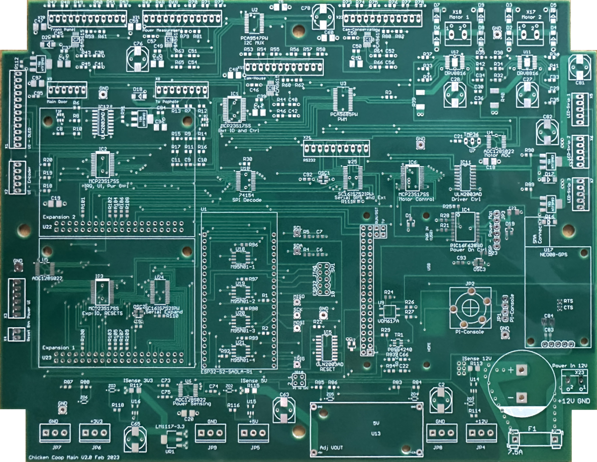
Main Board
This is the main board. The 4 external interfaces are at the top, motor drive top right. The left side has the user interface TFT and encoder. Bottom left are the buttons and indicators for the front panel. Across the bottom are screw terminals for various power rails and on the right going upwards, there is the main power in feed, then the LED strip connectors. Left to right in the centre of the board are the two expansion sockets, then the ESP32 socket, the Raspberry Pi socket, the oversized 3.5mm vertical jack for the Pi's serial console, and finally, the GPS module.

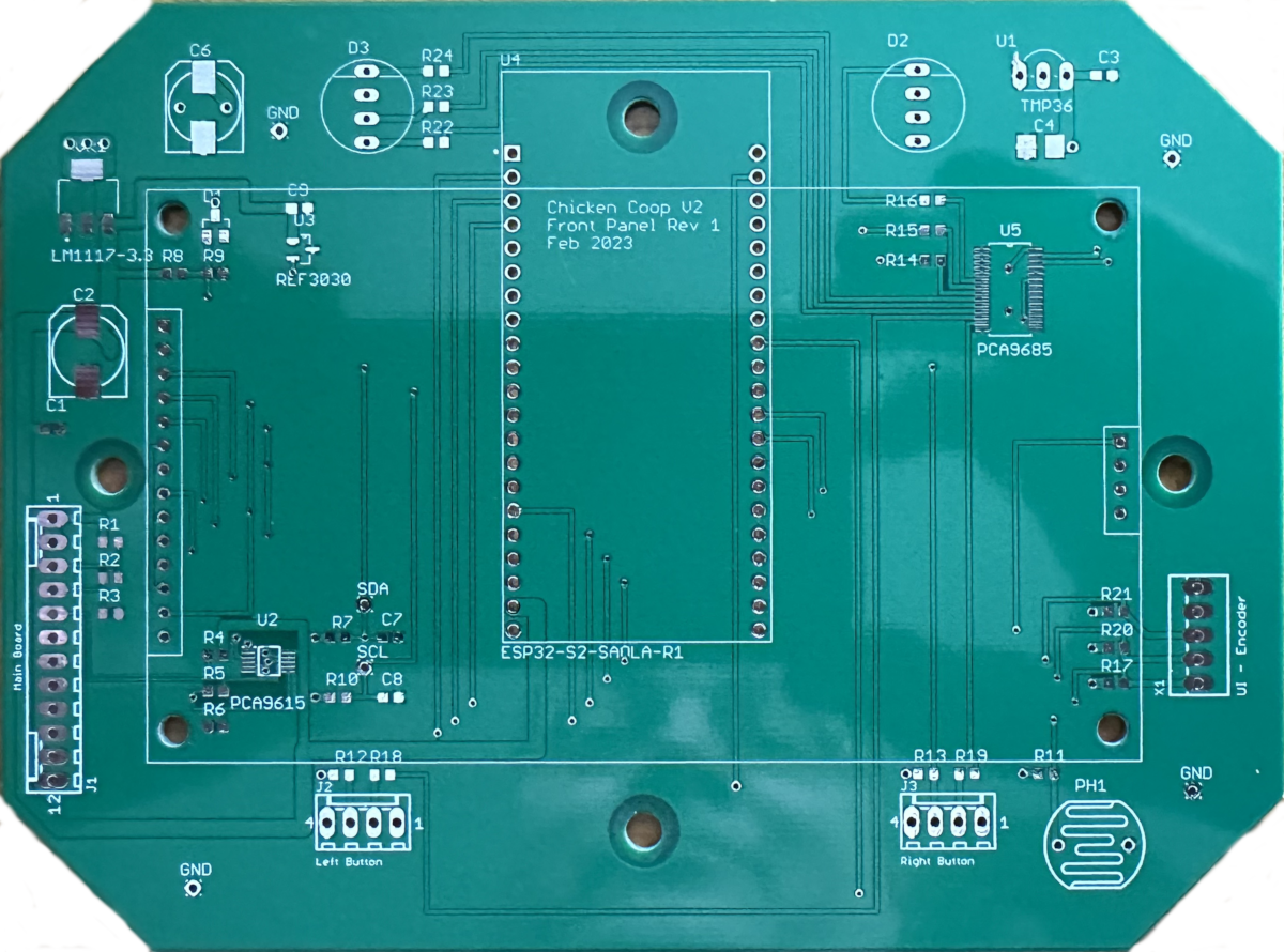
Front Panel
The next board is the front panel. The interface from the main board is on the left, centre is the ESP32 socket and the large footprint is for the TFT display. At the top are two tricolour LED's and at the bottom are two connectors for switches and LED's. On the right is the rotary encoder connector.

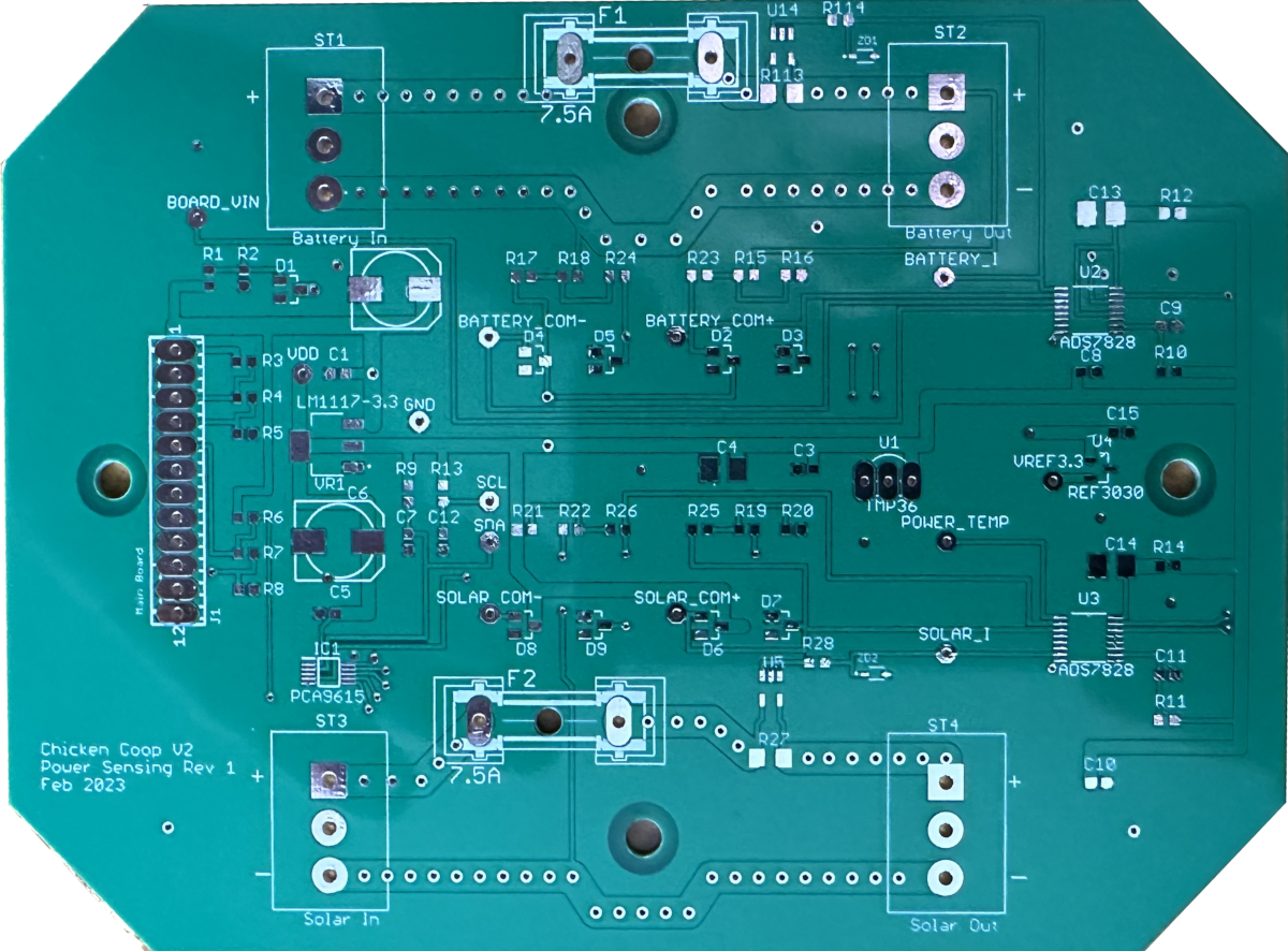
Power sensing
The final board is the power sensing board. On the left is the interface from the main board. The rest of the board can be seen as a top and bottom power channel, with the large connectors for screw terminals for the positive and negative power traces, the fuse for each can be seen on the positive rail. The centre of the board has the sensing components and the ADC's are on the right, one for each power channel

Now all I have to do is to build them, test them, build the software, test it and I'm done. If only it was that easy.
