
All the recent work has been focused on getting the coop prepared and repaired, then installing the new hardware. As a result, some things had to give and were not completed before installation, this is not a problem as software updates are easy compared to all the maintenance and hardware installation. One casualty of the installation milestone was the front panel, since it got complicated and the amount of code and re-testing was going to be fairly high. To understand this, lets start by reviewing how the front panel works.
In the previous controller, the front panel was directly controlled by the main unit and it only had simple LED's, some push buttons and a couple of sensors for temperature and light level. There was no local intelligence and the code on the main unit was very simple.
A great feature that the original code has was the throbbing HEN 9000 LED in the centre of the panel, since this was driven by PWM and the LED throbbed - the brightness going up and down as if it was breathing. This gave an immediate view as to if the controller had crashed, since in a failure, the throbbing would stop. During a reboot, it would flash a couple of times to show where it was in the boot process.
On the new system, its very different. There is a local ESP32 S2 processor, it has a local I2C bus for a PWM controller, that can be used to drive all the LED's, both the tricolour ones at the top and the single colour ones at the bottom, it can also drive the backlight on the TFT display, providing a dimming capability, this is consistent across all the LED's and all the TFT's in the system. There are also some push buttons on the unit and a rotary encoder that form the input part of the user interface, these go direct to the local ESP32.
A local SPI bus is used to control the TFT display, its purpose is to significantly improve the user interface. The TFT also has a touch interface and an SD card reader, but neither of these are in use, since I want micro SD support, not full size SD card. The SD card reader doesn't have any insert switch either, but more on that later.
There is a second I2C bus that connects only to the main unit, hence the main unit can't see any local devices on the module and it has no direct control over them. This is deliberate to ensure isolation of responsibilities and its detailed in the board standards.
Managing the front panel
Being that this module has a local processor, it also has its local firmware, thus the usual Over The Air (OTA) firmware update method is used. There is however nowhere to connect a serial console, nor any way to directly get to this from a command line perspective and that will in time be a problem that involves a pair of wellie boots to fix. The current approach is to develop in the office, get the firmware to the required level, then send it to the Coop. If there are any problems, the TFT is removed, the ESP32 is removed, re-programmed in the house, and re-installed. Its hardly ideal, but its easy to fix and is a good thing to remember before you push new firmware.
The initial code base was derived from the main unit, with all un-necessary functionality stripped out. This gave a quick start for the front panel module, up to the point of how it would communicate with the main unit. After careful consideration and recognising that I'll want to use the same approach on other forthcoming modules, I came up with the following principles.
- As the front panel device is effectively just another I2C device on the bus, it must follow the standard I2C bus approach, which has already been described previously, but in principle :
- A bus master sends commands to a slave unit and the slave unit responding when the master initiates communication.
- An interrupt pin on the connection to the main board allows any remote module to request the attention of the master unit.
- A reset pin on the connection to the main board allows the main unit to return the module into a known state.
- Like other I2C devices, they can be self sufficient during normal operation, getting themselves into a properly initialised state during initial start-up. This requires no external influence.
- The remote modules must be self sufficient
- They need to be able to manage themselves without any connection the main unit, this makes testing and diagnostics easier when testing locally.
- The module can, in that mode use the local resources as it wants to, for example displaying information on the display, etc. However, once the main unit connects to the module, it must:
- Reset all the resources to a known initial state, so that the master node doesn't have to consider what the module was doing prior to connection
- Obey the commands its given and not interact with local resources without being instructed to do so
After a bit more thinking, I decided that I needed a set of registers for the master to access, in the same way that other I2C devices work. Some would be read write, some write only, others read only. This is exactly the same as many other devices have already solved this problem.
Multiple registers were created for functions including :
- A health register, providing a periodic heartbeat, allowing the module to know that the main unit is present and if its connected / working locally. This is also really useful in allowing the module to check if the main unit crashes, since it can display a local error message and potentially alert me to the failure if no heartbeats are received over several seconds, but more on this in a future article.
- An Interrupt register, showing which of the capabilities need some attention. This allows the module to let the main unit know if a sensor has changed by more than an allowed amount.
- Examples are the temperature changes by a certain percentage, the light level changes, the input voltage changes, etc. This is necessary to ensure that the bus bandwidth is conserved and not wasted by noise level changes on any remote sensor.
- A diagnostic register, allowing the main unit to request a local self test of the module and report any errors. This may be a self managed diagnostic, or a more detailed diagnostic, requiring user interaction, pressing buttons at various times, confirming if certain things happened on the board (lights went on to a specific colour, the screen cleared, etc).
- One for each capability on the board
- Simple LED's - on/off, fade on, fade off, flash, etc
- Tricolour LED's - on in any colour, off, fade on, fade off, flash two different colours, etc
- Buttons, allowing the button states to be sensed, pushed, not pushed, double click, long click, etc so that intents can be given on actions including :
- Click = primary action, confirming, OK, Enter, etc.
- Double click = Back to previous
- Long click = Secondary action
- These examples are primarily for the rotary encoder button, but it gives an example of the flexibility a single button can provide.
- The rotary encoder, turning right, turning left, speed of rotation. Button presses are handled in the button object, just as a different button ID
- A register per analogue sensor
- The light level, the temperature, the boards input voltage,
- The number of bytes required to transfer this must be minimal to conserve bus bandwidth and the data format must be consistent across all modules, so no doubles or floats on the wire.
A proprietary 16 bit data format was used in the older code base for similar bandwidth conservation reasons, its called a PseudoFloat, this encodes floating point data in a fixed 16 bit value, providing more accuracy than required for any given sensor. This data type will be carried forwards, since it works well.
In effect, its a float that is multiplied up by a fixed factor of 100, to get to a sufficiently detailed integer value, which can then be sent as an signed integer, this value is then transmitted.
On reception, the value is converted back to a float and then divided by 100, to recover the floating point component. The scaling factor is not carried in the message and must be known in the sender and receiver.
The choice of 100 provides 2 decimal places of accuracy, which is plenty for most sensors, as it allows for values in the range of +/- 327.68 to be expressed with an accuracy of 0.01
I'd already decided that the number of bytes written to the register was dependant on what the object was, some may need several bytes for a command, others only one. Again, copying how some other I2C devices operate, reading a 16 bit value from a device as an example. There is however, no concept of a register pointer nor it being incremented by each read or write operation. This is an alternative approach used by some devices, but in this case, it would make the interface far more complex, particularly if stings needed to be sent, The length of the string would dictate how many register bytes would be necessary and this could lead to more data on the bus, selecting larger register ID's.
Once I'd got to this point, the penny dropped on how to interface with the TFT display, I can use the same approach, just add a register for each of the Adafruit Graphics (GFX) functions and send the data in the same format as the functions expect. This requires keeping the library versions in sync between the main unit and front panel, but by this time I'd already started moving the libraries in Platform IO to use the Platform IO package Registry so that shouldn't be a problem as both modules will receive the same updates before a recompile.
This approach meant that the drawing a rectangle would need the same number of bytes that the Adafruit function definition dictates, which in this case is 5 int16_t or uint16_t types, two for the X,Y position, one for height, one for width and one for colour, so 10 bytes. Coding would be fairly easy too, since the only processing is to send the right formatted data from the main unit to the front panel, extract that on the front panel and then invoke the GFX library locally to make it write to the TFT and its done. This is simple to do, but needed some data structures to be made and shared between the two codebases, but on inspection of that, many were re-usable, such as point, a line, a rectangle, a circle, etc. This approach is also repeated in the Adafruit libraries.
The next problem was one of bandwidth, I2C is a relatively slow protocol, running at a speed between 1KHz and 5MHz, where the speed depends on a whole bunch of factors. Common bus speeds are 100KHz, 400KHz, 1Mbps, 3.4Mbps and 5Mbps, however both the sending and receiving devices must support these speeds. The NXP PCA9615 differential bus driver can go up to a theoretical 1Mbps when using a twisted pair cable for improved noise immunity. I am not using a twisted pair cable (in line with the board standards, to keep costs low), so my noise immunity will be far lower and as a result, the bus speed will be lower. This could be an upgrade, but would need two cables between the modules, rather than buying a custom (read expensive) cable.
The bandwidth problem is that the main module has a single I2C bus that is shared across all devices on the main board, across the 4 external modules and the two expansion sockets. The 4 remote modules have line drivers. Each boards limit will be the lowest speed of any single device in that chain, however bus speed can (and is) changed when switching between devices as this gives more effective bus time as sending 8 bits at 400KHz takes less time than 8 bits at 100KHz. I also have an NXP PCA9547 bus multiplexer on the board to reduce the length of the bus, which in turn reduces capacitance and therefore improves bus speeds and importantly, if one bus has a problem, it doesn't stop the whole system from functioning. However, since its a switching device, it also needs to be commanded over I2C to tell it which channel to use, this in turn takes a little time, but if used carefully, can be only once per per transaction to a module though.
The firmware on each unit is intelligent in that it knows the status of each device and will only write data when it needs to, not each time the code loops or that process unblocks. CPU cycles are plentiful and quick, compared to the I2C bus bandwidth.
Now I know how I'm going to solve the problem, I'm going to need to build the protocol and make it work on two different nodes at the same time, so out came the Saleae logic analyser to help me know what's happening on each module and therefore home in the inevitable bugs.
During this development, I run into a couple of challenges. The ESP32 and the Arduino Wire (I2C) library have maximum buffer sizes and if you overrun them, data is not sent properly since some data loss occurs. This happens since during a screen re-draw, many sequential commands are sent to the TFT and this just overruns the buffer. Rate limiting by inserting small delays works, but its not intelligent to. More work is needed to see how data can be buffered or the transmit buffer length determined before sending the next data, pausing when the buffer hits a high water mark, much in the same way that FIFO's and flow control is used in UART communication.
A further issue is that as the I2C and SPI busses are a shared resource, so one component hogging them is an issue for everything else and with two CPU cores, each core can be doing different things in different thread, and that would be bad as it would result in corrupted data on the bus, or garbled messages to remote devices. To solve this, Mutexes (mutual exclusions) are used on the I2C and SPI busses to ensure that another process does not try and write half way through someone else's transaction. In effect, only one task can have the baton at any time and if you can't get the baton when you ask, then you must wait a bit until the previous task gives it back.
After a bit of work, and progressing through each of the sensor types, finishing on the TFT display, things jump into life and the difference in user interface is amazing. There are a few bugs still to squash, such as buffer lengths and how to get back in sync if things go out of sync for any reason, but these are infrequent events.
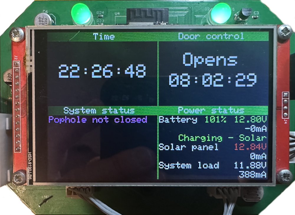
If you spotted the 101% on the battery level, this simply means that the battery is being charged, as the voltage is above the theoretical 12.8V fully charged level of a lead acid battery. The solar panel is showing as low, since its connected to the same bench power supply as the battery input, so far less than the typical 22V output of the panel.
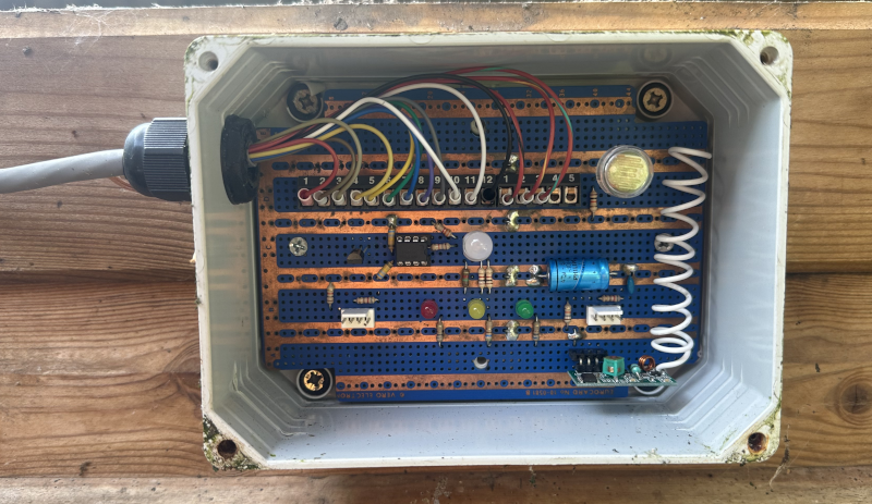
For comparison, here's the old user interface, just 4 LED's, one for overall system status and a traffic light arrangement for power, covering both battery and solar health. The central LED was to enable me to implement HEN 9000. The difference is night and day. The main led below is now the top left tricolour LED and the three lower LED's are now integrated to the top right tricolour LED. The error messages are displayed in human readable text in the system status section of the panel.
Alternative data transfer methods
During the development of the user interface protocol, I started thinking about alternative ways to get larger volumes of data between modules. Each protocol has pros and cons. I2C is slow, but simple and cheap to implement. SPI is fast, but short distance only (on the same board) and needs a dedicated chip select (CS) per device. But there are other alternatives. Espressif has a protocol called ESP-NOW, which uses Ethernet broadcast traffic to send messages to other nodes, without needing to have a WiFi access point, it can also work over Bluetooth, which would be ideal to allow modules to talk to each other. However, the ESP32-S2 doesn't have Bluetooth and the ESP32 S3 only has BLE, not classic Bluetooth. ESP-NOW, being proprietary, won't work on Raspberry Pi's. Similarly, being just plain Ethernet, there is no real security in it, so it can only be used for insecure content.
The other possible option for messaging is Message Queue Telemetry Transport (MQTT), which is used extensively within IoT solutions, and this system could easily be seen as one, but MQTT needs a broker such as Mosquitto to handle all the communication between all of the nodes. It can however handle large payloads, has methods to structure messages, security and its fast and can even request that a message is sent if a node dies, this is called a Last Will and Testament (LWT). The problem with this protocol is that it needs network access and the broker to be available, so its no good for stand-alone operation in the core of the platform.
The benefit of moving larger data volumes to faster protocols is that the I2C bus bandwidth can be preserved for the things that really need it. More work will be required in this area as additional modules come on-line. The key thing to remember is that the core of the system must function autonomously, without any dependencies outside of the coop its self. Main unit to front panel communications is critical to that, and this means that MQTT can't be used for that module. ESP-NOW however could, with limitations.
The I2C bus could however be used for sending things like passwords, certificates, encryption keys and other such one-off data securely between nodes to configure them, then switch to higher bandwidth protocols for larger data volumes, using the keys that were passed securely before.
Further work is required to determine how much faster the front panel I2C bus between the main module and front panel module can go over straight (non-twisted pair) wire. Faster communications means that the buffers will clear more quickly and that would also help with the issue identified previously in this article.