
The ESP32's are fantastic devices, evolving from the earlier ESP8266 microcontrollers, they generally have many more resources such as RAM and FLASH, compared to other equivalent microcontrollers of the day, along with many device functions that simplify interfacing in any design. The problem is that some of these device functions come and go over time and newer device types are always in the pipeline. Good examples are the Ethernet Media-Independent Interface (MII), for physical Ethernet connections or Bluetooth, which were on the ESP32, but not on the ESP32-S2. This happens since space on the silicon die is limited and sometimes more important things cause the eviction of less useful / less used capabilities.
I had seen that the ESP32-S2-Saola-1 devices were being discontinued and replaced by the ESP32-S3 devices, but, having already purchased of more than 15 of the S2's and having already based my design on the S2's, I decided to go with what I had available, rather than what was coming next, otherwise we will always be chasing the next greatest thing. Additionally, the footprints between them are not the same and their pinouts are not the same either, so I can't just drop in the next version and move on. Its also important to remember that in 12 months, any product will probably be obsolete and buying a generation back will, in many cases give you more value as the older products are often cheaper to clear them in the channel.
During software development, at the end of the build, it shows the amount of FLASH and RAM being utilised and I could see the allocation bars gradually creeping up and I know that I want to get some additional functionality into the devices in later firmware releases, such as an SSH console in addition to the UART one, hence allowing me to connect directly and get rid of the Pi. The problem with that is that I'll need some certificates and those need to be stored somewhere and they are fairly large in size - several KB each. The SSH libraries are also quite large.
I know that the standard ESP32 approach has two partitions for firmware, allowing in-place firmware upgrades and roll-back if things go bad (more on this later in the article). It is possible to remove this feature and get double the capacity of FLASH, just with limitations for maintainability. Its also know that removing the Arduino framework is supposed to free up quite a lot of FLASH space, according to others that have already done it, however, this design is not ready to make that change yet and I don't want to loose the in-place programming capability either, so other, less invasive alternatives need to be considered.
I started looking at the design and considering what next, particularly as I haven't installed the unit yet, could I upgrade in some way to an ESP32-S3 on the main unit, maximising flexibility and keeping the ESP32-S2 in the front panel module. The wheels started whirring and I came up with the approach of an adapter board that converted one to the other, allowing for the best of both worlds. I also updated my next board version to support ESP32-S3 devices, although I already know that by the time that happens, that will be obsolete and I'll have to update to what's available at that time, its a bit like ordering the soup of the day, you never know what it is until you ask on the day.
The result was this adapter, its an ESP32-S2 to ESP32-S3 adapter and its an ESP32-S3 to ESP32-S2 adapter, so I can upgrade existing boards and use some of the older chips in newer boards, allowing me to build new boards with new sockets on them if I want to. The only thing is that its a one-way thing when they are assembled, since the connector positions and pin positions is what dictates the direction it will operate in.
The picture below shows one of each, with the S2 to S3 adapter on the left and the S3 to S2 adapter on the right, along with an S3 device inserted, since I picked a couple up to see how much better they were.
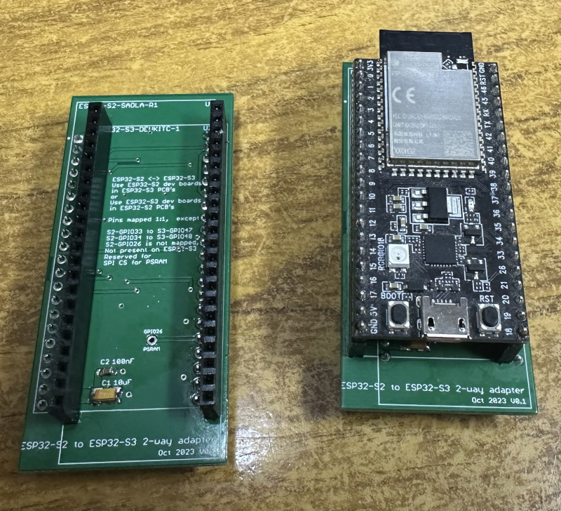
The main differences between the S2 and S3 chips is that the S2 is a single core device, whereas the S3 is a dual core device, each using Xtensa 32 bit LX7 CPU cores running at the same 240MHz clock rate. RAM is increased from 320Kb to 512KB and FLASH is increased from 128Kb to 384Kb, but external FLASH can also be added and on the ones I have, have 8Mb of FLASH, although as noted above, this is partitioned down for different things, such as two firmware partitions, to allow upgrades and fail-back, boot loaders, Preferences storage and other chip specific information. This is partly why the S2 was problematic for me, even with its 2Mb external FLASH, I had less than 512K for my code to live in.
The S3 has a Bluetooth 5 LE, which should in theory let me have a Bluetooth connection to other devices in the coop and that could be handy in the future, as could ESP-NOW mesh networking over Wireless, without needing an access point. These are all things that need looking at in time and were added to the project backlog.
A small number of pins differ between the two chip versions and one pin, which in my mind should never have been pinned out on the ESP32-S2 is the GPIO 26, which is connected to the Pseudo Static RAM (PSRAM), if its fitted and this will cause you problems if you connect something to it, even if you don't use PSRAM. Ask me how I know. The remaining ones are different, but can easily be catered for by updating the source code to just use the different GPIO number
You may note that there are two USB sockets on the S3, since JTAG programming is out of the box with no custom header and no need for the ESP-Prog JTAG interface that the ESP32-S2 requires, this feature is really useful and means that I can now recover the board from outside the case, if I connect a USB connector to the ABS box in some form of waterproof / dustproof manner, if you look on the previous article showing the ABS boxes, this is the bottom left, rectangular hole, since as luck would have it, a friend who has similar background and they were clearing up and had a couple of waterproof USB sockets going spare, which were traded for a couple of pints at the local tavern.
A side effect of using the newer S3 and the adapter board is that some pins that were in use, such as USB D+ and USB D- are those now used on the second JTAG interface, meaning that some re-mapping of pins on the main PCB was also necessary and the JTAG port and associated pins are now not required and can be re-mapped.